6" I.D. Standard Industrial Pitless Units-NSF 61 Certified

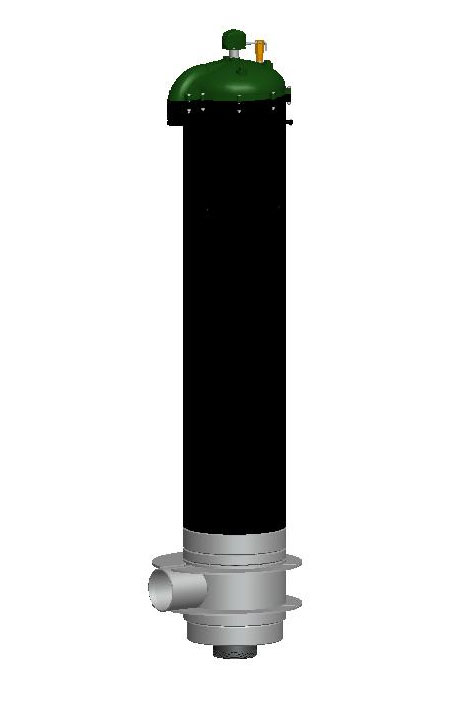
6 inch standard pitless unit Click the images to view full size

EXPLANATION OF PITLESS UNIT ORDERING NUMBERS
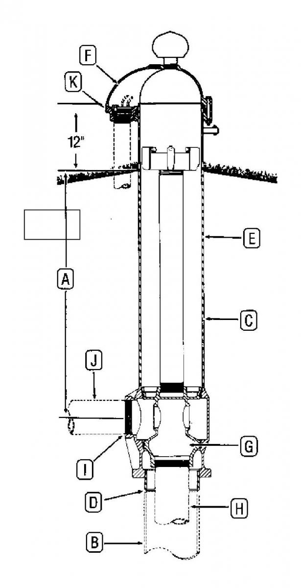
The diagram illustrates the meaning of the various letters and numerals used in Monitor Standard Industrial Pitless Unit ordering numbers. A typical order number and the pitless unit it stands for are shown.

 
  • Features
  • Specifications
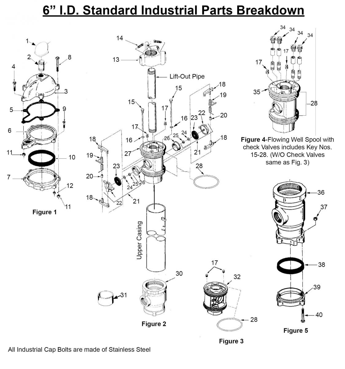
  • Parts Breakdown
  • Component Materials
  • Ordering Instructions

CORROSION PROTECTION — all water passages are either hot-dipped lead free galvanized or constructed of corrosion resistant material

EASY TO SERVICE — Well cap can be removed without disconnecting cables. O-ring seals on spool permit withdrawal of the entire inner assembly simply by lifting. Replacement is equally simple. Spool support eliminates vertical adjustment and any possibility of dropping the inner assembly into the wall.

RELIABLE SEAL — Neoprene O-Rings between accurately machined hot-dipped lead free galvanized surfaces on the spool and within the unit provide positive seals.

O–RING SEAL PROTECTION — Monitor seal protection prevents seal damage during installation and service.

FROST PROOF — No Heating is required

QUICK TO INSTALL — A quality pump installation can be made easily and economically without delay for masonry or building construction

ALTERNATIVE SPOOLS — Spools are available plan (EO) or with silent check valves (E2-Double)

WATERTIGHT WELL CAP WITH SCREENED AIR VENT — Designed to permit removal without disconnecting cables. Watertight cable and conduit sealing is optional

HOLD-DOWN — Supplied with each unit. Hold-down pipe also serves as lift-out pipe for installation and servicing.

REINFORCED O-RING LANDS — Cast in to prevent discharge body from becoming out of round

DEPTH TEST BLOCK — Standard on all units


OPTIONS

SEALED CONDUIT CONNECTION — Watertight conduit seals made of neoprene are available for most common cable sizes. (Round Wire Only)

EPOXY PAINTING — Can be done, if required for extra protection in certain soil types

ADDITIONAL TAPPING IN SPOOL

TRANSITION SLEVE FOR MECHANICAL JOINT DISCHARGE

FLOWING WELL UNITS


Available in Stainless Steel upon request

6 Inch Industrial Pitless
A Screened Well Vent tap size: 1-1/2” NPT
B Seal Cap: The Watertight cap bolts to a compression seal ring securing around the
pitless case and comes with the screened well vent installed.
C Conduit Tapping size:
Watertight conduit seals for most common cable sizes are available for watertight cap.
1-1/2” NPT
D Depth Tester Tapping: 1/4” NPT
E Distance from ground level to top of Pitless Case: 12”
G Distance from ground level to top of
Screened Well Vent:
19-1/2”
H Pitless Case I.D. size: 7”
I Pitless Case wall thickness: .300”
J “Hold-Down” - “Lift-Out” Mechanism
Three set screws in a spider atop the “Hold-Down” - “Lift-Out” pipe brace against the interior of the pitless casing, locking the spool in place.
Hold-Down, Lift-Out pipe size (Schedule 80):
Designed “Lift-Out” Mechanism load:
2” NPT
15,000 lbs.
DISCHARGE BODY - THREADED
K Discharge Body outside diameter: 9-11/16”
K Discharge Body length:
DISCHARGE BODY - KWIKONECT
11-1/4”
K Discharge Body outside diameter: 10”
K Discharge Body length: 12-9/32”
L Pitless Unit minimum inside diameter.: 6-3/8”
M Discharge Connection Tapping size: 3” NPT
N Pitless Unit to well casing connection I.D.: 6” Weld
O SPOOL ASSEMBLY
Spool Design Load:
15,000 lbs.
P MOTOR CABLE PASSAGES THROUGH SPOOL 13/16”
Q 1-3/4”
R Spool to Drop Pipe Connection: 3” NPT
S Pressure zone tapping: 3/8” NPT: (2) available
T Dimension from center of discharge outlet
to bottom of weld nipple:
9-3/8”
U Overall length of seal cap: 12-7/8”
V Dimension from center of discharge to
bottom of discharge body:
7-3/4”
W Dimension from center of well casing to
end of discharge outlet:
5-25/32”

Specifications are Subject to Change Without Notice.

For Flowing Well spool concept, see Booster Station section.

*Optional flange, weld or mechanical joint available upon request.

Note: Pitless units conform to the Recommended Standards for Water works, Great Lakes Upper Mississippi River Board of State Public Health & Environmental Managers and Water Systems Council PAS-97 (04) Standards.


COMPONENT MATERIALS
Well Vent - cast iron, green enamel finish.
Cap & Conduit Box - cast iron, green enamel finish.
Hold-Down Spider - cast iron, green enamel finish.
Hold-Down Pipe, 2” - steel Sch. 80, black.
Pitless Case - steel, black.
Spool - cast iron, lead-free galvanized.
Discharge Body - cast iron, lead-free galvanized.
Check Valve Body & Arms - brass.
Check Valve Seat - Brass.
Check Valve Spring - Monel.
Compression Seal Ring & Check Valve Facing - Neoprene.
Electrical Conduit Cable Seal - Neoprene.
Maximum Rated Discharge Pressure - 300PSI

The drawings and parts list apply to the model numbers listed below.
See drawing.
Note: Add (F) at end of model number for flowing well unit.
Bury Depth
Unit
Well Size Tap
Case Size
Well Casing Attach.
Upper Case
Cap Style
Spool
Drop Pipe I.D.
Drop Discharge Conn.
Discharge I.D.
1’ & Up
PS
6”
7”
W
B
W
E0
3
T
3
1’ & Up
PS
6”
7”
W
B
W
E2
3
T
3
1’ & Up
PS
6”
7”
N
B
W
E0
3
T
3
1’ & Up
PS
6”
7”
N
B
W
E2
3
T
3

6" Standard Parts Breakdwon

All units have a watertight cap with screened vent.

All Industrial Cap Bolts are made of Stainless Steel


Monitor Pitless Units listed above are equipped with
one of the following types of Spools:

E2 Spool with check valves, Figure No.2
E0 Spool without check valves, Figure No. 3
E2 Spool with check valves for Flowing Well, Figure 4
E0 Spool without check valves for Flowing Well, Figure 4
Note: Optional Cable Seals available.

Key No.
Ordering Number
Description
Quantity
FIGURE 1
-----
7WPSM
Watertight Cap, includes Key Nos. 1-12
-----
WBAG2
Pkg. of S.S. bolts & Nuts for Cap
1
1
PS150
Vent Assembly
1
2
PS263
Pipe Nipple
1
3
PS217
Seal Cap & Plug Assembly
1
4
PS93S
Machine Bolt, 3/8-16NC x 2 1/2” L.
1
5
PS197
Gasket
1
6
PS377
Retainer Ring
1
7
PS187
Depression Ring
1
8
PS94S
Machine Bolt, 3/8-16NC x 3 1/2” L.
6
9
PS132S
Machine Bolt, 5/16-18NC x 2” L.
2
10
PS167
Seal Ring
1
11
UB17S
Hex Nut, 3/8-16NC
7
12
PC434S
Hex Nut, 5/16-18NC
2
FIGURE 2
13
UC129
Hold-Down Assembly, includes Key Nos. 13 & 14 assembled
1
14
UC139
Set Screw, 7/16-14NC X 1 3/4” long
3
15
UC299
Hinge Pin
2
16
UC127
Hinge Pin Gasket
2
17
UN122
Pipe plug, 3/8-18 NPT
2
18
UC301
Valve Rocker Arm
4
19
UC302
Valve Spring
2
20
UC300
Center Coil Support
2
21
UC296
Check Valve Assembly, includes Key Nos. 22-25 assembled
22
UC292
Valve Body
2
23
UC295
Rubber Check Valve Facing
2
24
PS158
Brass Washer
2
25
PS159
Brass Nut, 3/8-16NC x 1/4” thick
2
26
UC293
Check Valve Seat
2
27
UC290
Spool only
1
27
7E2PS3
Alternate spool with check valves includes Key Nos. 15-28 assembled.
28
UC15
“O” Ring
2
30
UC291
Discharge Body
1
31
6AWN
Welding Nipple
1
FIGURE 3
32
7E0PS3
Spool without check valves includes Key Nos. 17, 28, 32 assembled
32
UC142
Spool, also includes Key No. 17 assembled.
1
FIGURE 4
-----
UC392
Flowing Well Spool with check valves (7E2PS3F - Boxed)
1
34
-------
Cable Seals (See Spools & Cable Seals)
35
UC393
Flowing Well Spool w/o check valves (7E0PS3F - Boxed)
1
FIGURE 5
36
UC491
Discharge body for kwikonect Style Units-not available for 6.6”
1
37
PC433
Hex Nut, 1/2”-13NC
6
38
PS166
Seal Ring
1
39
UC285
Depression Ring
1
40
UB201
Machine bolt, 1/2” x 13NC x 4 1/2” L.
6
6" Standard Pitless Unit
DESCRIPTION - ORDERING NUMBERS
A
3
Bury Depth in Feet
PS
Pitless Unit for Submersible Pump
B
6
spacerWell Size - Ins.
C
7
spacerUpper Case Size - Ins.
D
W
spacerAttachment to Well Casing-Welded
E
B
spacerBlack Upper Case
F
W
spacerWatertight Cap w/Screened Air Vent
E
spacerPressure Equalizing Spool Passages
G
2
spacerNo. of Check valves: (0 or 2)
H
3
spacerDrop Pipe I.D. Ins.
I
T spacerThreaded NPT Std. spacer
spacerConnection
Discharge
Connections
(Select One)
spacerFlange, ASA 150#
spacerWelded
spacerMech. Joint w/transition
spacersleeve
J
3
spacerDischarge I.D. Ins.
K
S
spacerElec. Cable Seal (S)
spacerO.D. 3 Wire____O.D. Grounding Wire____
spacerFlowing Well (F)
spacerSpecial Provision (X)


EXPLANATION OF PITLESS UNIT
ORDERING NUMBERS


The diagram illustrates the meaning of the various letters and numerals used in Monitor Custom Industrial Pitless Unit ordering numbers. A typical order number and the pitless unit it stands for are shown.
Typical Order Number
3PS67WBWE23T3S

3

A. The first numeral in the order number indicates the bury depth, in feet, of the unit. Bury depth on all units is measured from the center of the discharge line to ground level. The top of the pitless case extends 12” above ground level as is required by many codes. However, any length can be manufactured.

PS
These letters indicate the type of pump the pitless unit is designed for. The unit shown is a PS for submersible pumps.
6
B. This numeral indicates the well casing size, 6 ” I.D.
7
C. This numeral indicates the upper pitless case size, 7” I.D.
W
D. Indicates the attachment to the well casing is a welded joint.("N" for KwiKonect - 6" I.D. & 8" I.D. only).
B
E. Indicates the upper pitless case is black pipe.
W
F. Indicates the unit has a watertight cap with screened vent installed.
E
G. Indicates spool has pressure equalizing passages, for venting well.
2
Indicates the type of spool which the pitless unit has. In this case it is a spool having two silent check valves.
3
H. Indicates the size of drop pipe in inches.
T
I. Indicates the discharge connection is threaded.
3
J. Indicates the size of discharge pipe in inches.
S
K. Sealed Conduit Connection. (Optional)