
Custom Pitless Units - NSF 61 Certified
 Click the images to view full size
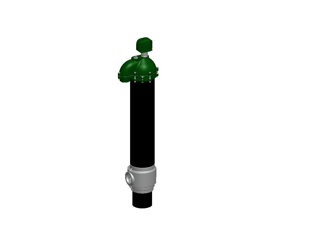
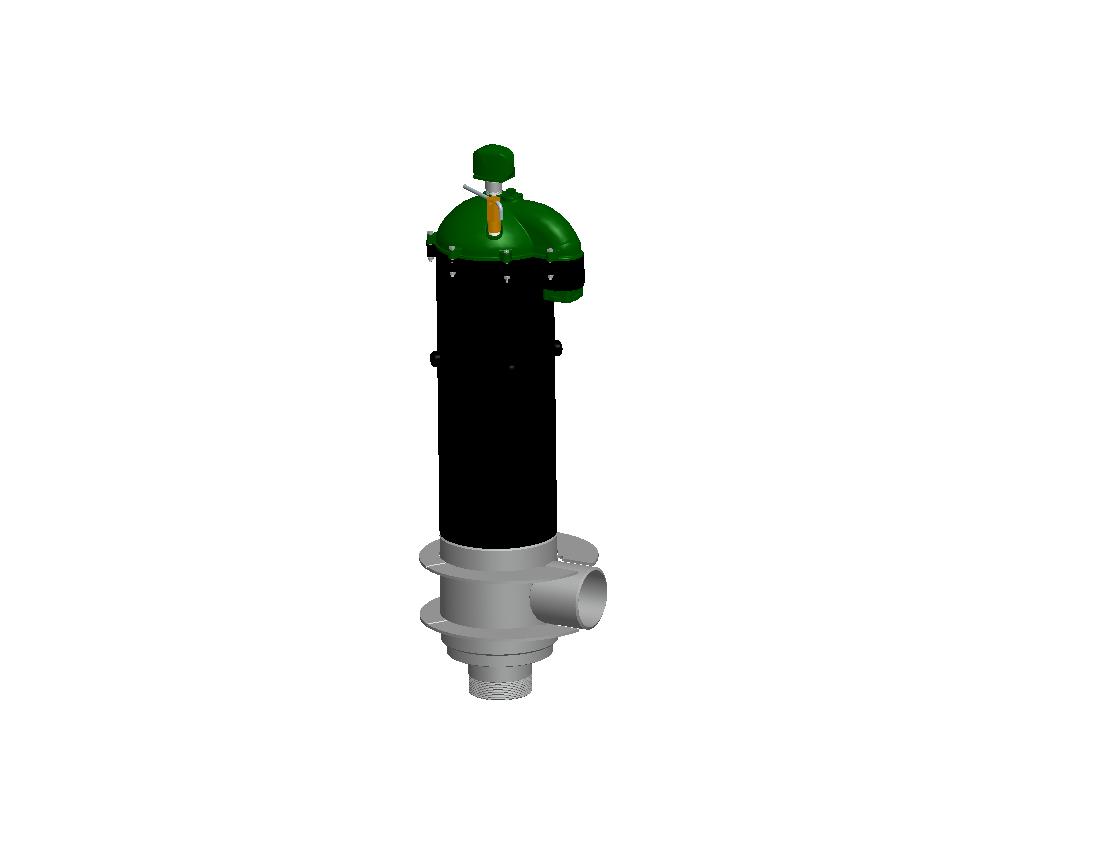
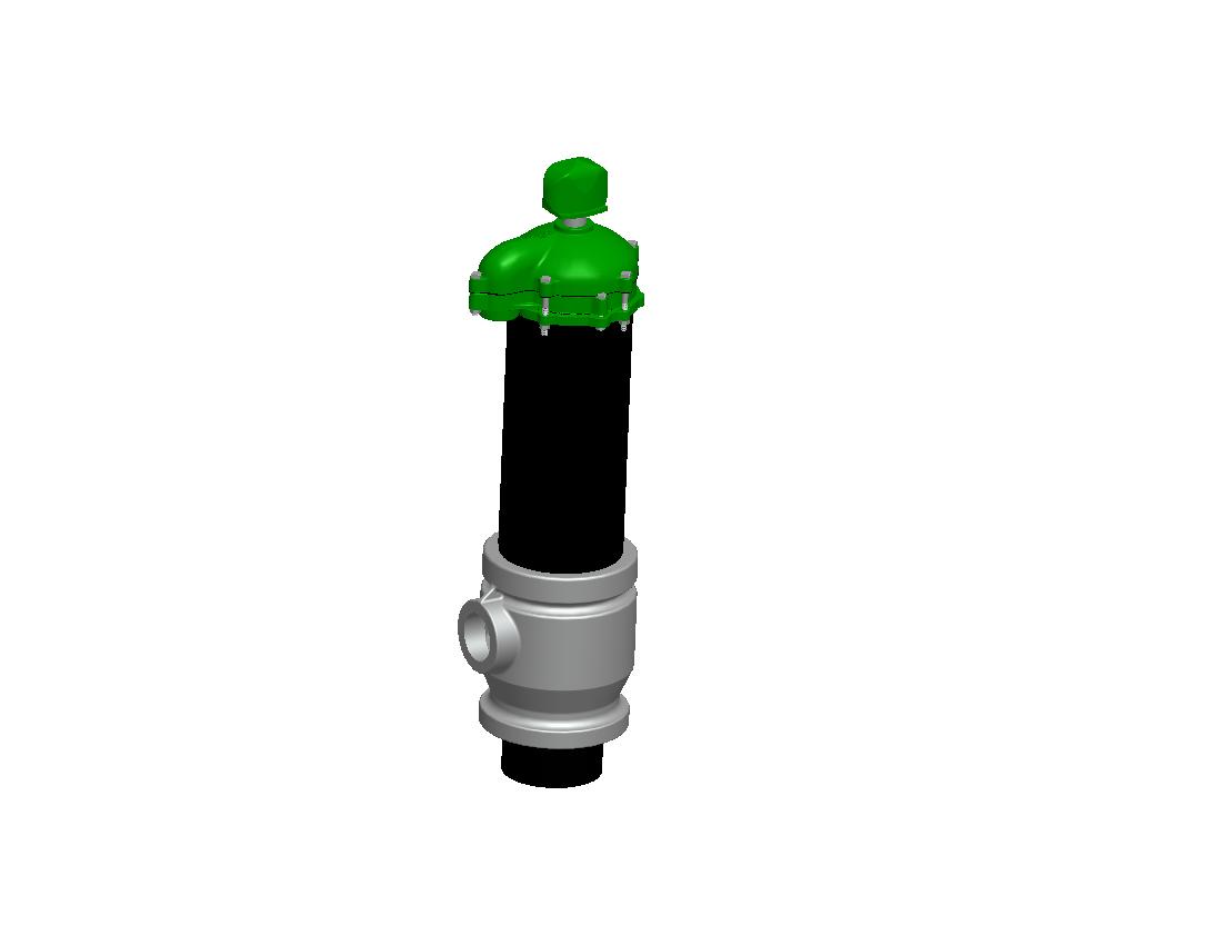
Fabricated from the highest quality materials, the Monitor Custom Pitless Unit is a safe and sanitary method of completing a Municipal / Industrial water well. The Monitor Custom Pitless Unit attaches to the well casing and provides a sanitary underground discharge to the water treatment facility.
Custom Industrial Pitless Unit Features and Options
NSF 61 Certified!
The spool and discharge body are constructed of high strength cold-rolled steel. Using lead-free zinc, the spool and discharge body are galvanized for long term corrosion protection. Upon request, the Monitor Custom Fabricated Pitless Units can be fabricated from stainless steel. Our Custom Pitless Units are available for the following well diameters: 10”, 12”, 14”, 16”, 18”, 20”, 22”, 24”, 26”, 28”, 30”, and 36”.
Monitor Custom Pitless Units are shipped as complete factory pressure tested pitless unit including the Watertight Premium Well Cap, Upper Bury Depth Casing Extension, Discharge Body, Spool, Discharge and Drop Connection, Lift-Out Bail, and Hold-Down Assembly. Available options: epoxy coating, API drop pipe and discharge threads, cap cable seals, flowing well spools, locking seal caps, flanged upper casing, water sampler valves, wire seals, dual zone pitless with recharge lines, probe tubes, and additional conduit entrance connections for signal wires.
- Installation Instructions
- Shipping Weights
- Spools And Cable Seals
- Sealed Conduit
- O-Ring Selection Guide
For CAD drawing contact sales at 800-356-5130 or e-mail monitorsales@baker-mfg.com.
- Features
- Specifications
- Parts Breakdown
- Component Materials
- Ordering Instructions
* For All Sizes
CORROSION PROTECTION – all water passages are either hot-dipped lead free galvanized or constructed of corrosion resistant material
O-RING SEAL PROTECTION – Monitor seal protection prevents seal damage during installation and service.
FROST PROOF – No Heating is required. All water passages are below the frost line.
QUICK TO INSTALL – A quality pump installation can be made easily and economically without delay for masonry or building construction
EASY TO SERVICE – Well cap can be removed without disconnecting cables. O-ring seals on spool permit withdrawal of the entire inner assembly simply by lifting. Replacement is equally simple. Spool support eliminates vertical adjustment and any possibility of dropping the inner assembly into the wall.
RELIABLE SEALS – Neoprene O-Rings between accurately machined hot-dipped lead free galvanized surfaces on the spool and within the unit provide positive seals.
WATERTIGHT WELL CAP WITH SCREENED AIR VENT and LOCKING BOLTS – Designed to permit removal without disconnecting cables. Separate junction box is eliminated. Watertight cable and conduit sealing is optional
HOLD-DOWN – Supplied with each unit. Hold-down pipe also serves as lift-out pipe for installation and servicing.
SUPPORT RINGS – Prevent distortion of the Discharge Body due to vertical movement of Discharge Pipe
LOCKING BOLTS
LIFT-OUT BAIL
DEPTH TEST BLOCKS
PROTECTED SCREENED VENT
PROBE TUBE
FLOWING WELL UNITS (available for most well sizes)
WATER SAMPLING VALVE-FROST PROOF (optional)
All units are available in Stainless Steel upon request.
PART 1 GENERAL
1.01 SUMMARY
A. Section Includes:
Complete assembled Pitless Unit System including well cap, lift-out bail, hold down hooks, lift out pipe, discharge body with support ring, spool with or without check valves and pressure equalizing passages.
1.02 SUBMITTALS
A. All bidders shall submit as part of their bid:
1. The Manufacturer and Model of the Pitless Unit to be installed.
2. Detailed Specifications with Drawings of the System furnished by
the manufacturer.
PART 2 PRODUCTS
2.01 PITLESS UNIT
The Pitless Unit shall be equal to Baker Manufacturing Company, Monitor Division, Model_____________________________________. The unit should be factory assembled, before shipping to the site. The pitless unit must conform to the Recommended Standards for Water Works, Great Lakes Upper Mississippi River Board of State Public Health & Environmental Managers, Health Education Services, Albany, NY., and/or Water Systems Council PAS-97 (04).
2.01.01 WELL CAP
The Watertight Cap shall be secured to the pitless casing with a compression gasket. The top of the cap can be removed without affecting the sealed conduit or wiring. The heavy duty watertight cap will have a separate protected downward facing screened well vent with pipe nipple. Construction of the cap and well vent will be of heavy duty gray cast iron and painted with a green enamel finish.
2.01.02 UPPER CASING
The Upper Casing is factory assembled to the discharge body, and the lift out and hold down mechanism are factory assembled to the spool. Upper casing thickness must conform to the Recommended Standards for Water Works, and be coated with a rust protective coating. The upper casing must provide a watertight connection from the discharge body to the well cap. The discharge port center line to be_______________ feet below grade, and the pitless upper casing to extend ________________feet above grade.
2.01.03 SPOOL
The spool shall include _______________NPT per ANSI B 1.20.1 male or female drop pipe connection and shall be constructed of lead-free galvanized heavy duty gray cast iron, ductile iron, or steel with a lead-free galvanized plating on the wetted surface of over .010 inches thick. The spool will have o-ring grooves machined into the spool retaining the o-rings when setting or pulling the system.
The positive pressure o-ring seals shall be constructed of neoprene or equivalent. Spool shall be designed to accommodate probe tubes or water samplers and NPT ports for discharge pressure taps. O-ring protection should be provided to prevent the seals from dragging on the upper casing when the pump is installed or removed.
2.01.04 DISCHARGE BODY
The Discharge Body shall be constructed of lead-free galvanized ductile iron or lead-free galvanized steel. O-ring seat to be designed to prevent crevice and galvanic corrosion, dissimilar metals should be avoided. Discharge body designed to be strong enough to prevent distortion due to vertical movement of discharge pipe thereby allowing spool to bind in the discharge body. Minimum I.D. of the discharge body to be equal to or greater than I.D. of the well casing for ease in well servicing.
2.01.05 HOLD-DOWN MECHANISM
The Pitless Unit spool should have a hold down mechanism, factory assembled to spool and capable of preventing rotation of the pitless spool relative to the discharge body, at full rated locked rotor torque of the submersible pump motor. The spool must also have a factory assembled lift out pipe and bail, or spider capable of ___________lbs. rated load, to allow lifting a water filled drop pipe and pump out of the well for service. Components to be constructed of ductile iron or steel with a corrosion resistant coating.
2.01.06 CHECK VALVES (Optional)
Optional Check Valves may or may not be provided in the removable spool of the pitless unit. These should be low pressure drop, self cleaning, swing type check valves, with elastomer seal at seat, and constructed of corrosion resistant materials.